We designed the Bessify Energy System from first principles around one question: what happens when a cell fails?
The US Department of Energy defines thermal runaway as “an accelerating release of heat inside a cell, due to a series of exothermic reactions” that becomes “an exponential, uncontrollable, increase in cell temperature”, and warns that its propagation “can lead to major system fires or explosions.”
Source: US Department of Energy, Office of Electricity, Energy Storage Safety Strategic Plan, April 2024.
A cell can fail. Prevent that failure from spreading
Bessify combines cell quality control, continuous monitoring and physical separation with two active propagation-prevention functions.
Electrical isolation removes an external energy path, but it cannot stop the internal reactions of a failing cell. Protection therefore extends beyond shutdown.
Bessify TRPPS
Multi-layered propagation prevention
Bessify is designed so that propagation control is applied at multiple levels by the Thermal Runaway Propagation Prevention System (TRPPS). TRPPS 1 actively manages the initiating thermal-runaway event to prevent cell-to-cell propagation. TRPPS 2 provides an independent water-deluge and inundation response to arrest further propagation if its configured trigger condition is reached.
Neither claims that a cell cannot enter thermal runaway.
TRPPS 1
Active cooling and gas management
When abnormal behaviour reaches the configured activation condition, TRPPS 1 increases gas circulation and brings cooling to maximum capacity to protect neighbouring cells. The Thermal System also manages the compartment atmosphere if a cell releases gases.
The priority is to protect neighbouring cells, even if the initiating cell’s failure continues.
TRPPS 2
Water intervention
If TRPPS 1 does not arrest propagation, TRPPS 2 delivers water deluge and progressive flooding into the Energy compartment.
Physical architecture
Why we separated the system
A 2024 analysis by EPRI, PNNL and TWAICE attributed 89% of classified failed elements to controls and balance-of-system components, rather than cells or modules.
Separate potential ignition sources from the cells
Bessify places active power electronics and thermal-management equipment in separate compartments from the stored energy. Within the Energy compartment, electronics are limited to low-voltage temperature and voltage sensing. This reduces potential sources of fire and heat beside the cells that could initiate thermal runaway.
Power
Conversion and isolation
PCS modules, switching and grid-facing equipment are confined to their own serviceable compartment.
Energy
Cells, heat exchangers and busbars
Cells, heat exchangers and busbars are held in controlled mechanical, thermal and atmospheric conditions. Electronics within the compartment are limited to low-voltage temperature and voltage sensing.
Thermal
Cooling and gas management
The equipment that moves heat and manages the compartment atmosphere is physically separated from the stored energy.
The cell arrangement is part of the protection
Bessify preserves paths for heat removal, water delivery and progressive flooding. Access for intervention is designed into the Energy compartment from the outset.
Separation also protects the investment
TRPPS 2 delivers water into the Energy compartment. Physical separation is designed to preserve the Power and Thermal compartments, limiting the extent of damage and the equipment that would need replacing.
The Thermal System
Designed for protection. Used every day for cooling
Bessify’s Thermal System was designed around the gas-management and heat-removal demands of a cell failure. That protective duty determined its capacity, which exceeds normal operating cooling requirements.
Normal operation
Cell cooling
The Thermal System manages cell temperature through inter-cell heat exchangers.
TRPPS 1 activation
Gas Management
The same equipment increases gas circulation and brings cooling to maximum capacity to remove heat and protect neighbouring cells. It also manages the compartment atmosphere if a cell releases gases.
Bessify Heat Exchanger
One thermal interface. Two operating modes
The inter-cell heat exchangers provide the heat-removal interface in both operating modes, supporting everyday cell cooling and increased heat removal during TRPPS 1 activation.
Before assembly
Every cell begins with a record
Each cell arrives with its manufacturer data and is measured again before installation. The record then follows that cell to its exact floor, row and position in the Bessify Energy System.
A cell that departs from its peers does not go in.
That traceability provides a baseline for comparison throughout life. Later behaviour can be tied to an individual position, production batch and incoming measurement.
01
Factory record
Capacity, internal resistance and shipping voltage, by barcode.
02
Re-measured on arrival
Each cell re-scanned and its voltage re-measured after shipping.
03
Resistance baseline
A six-second direct-current resistance test, recorded.
04
Scanned into place
Floor, row and position in the row. Every row retested before the next floor is built.
Measure the cell, not the terminal
We opened one to see where temperature should be measured
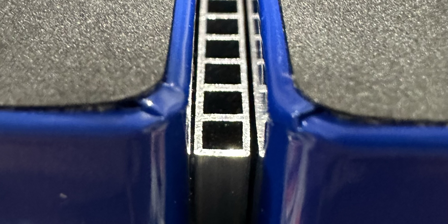
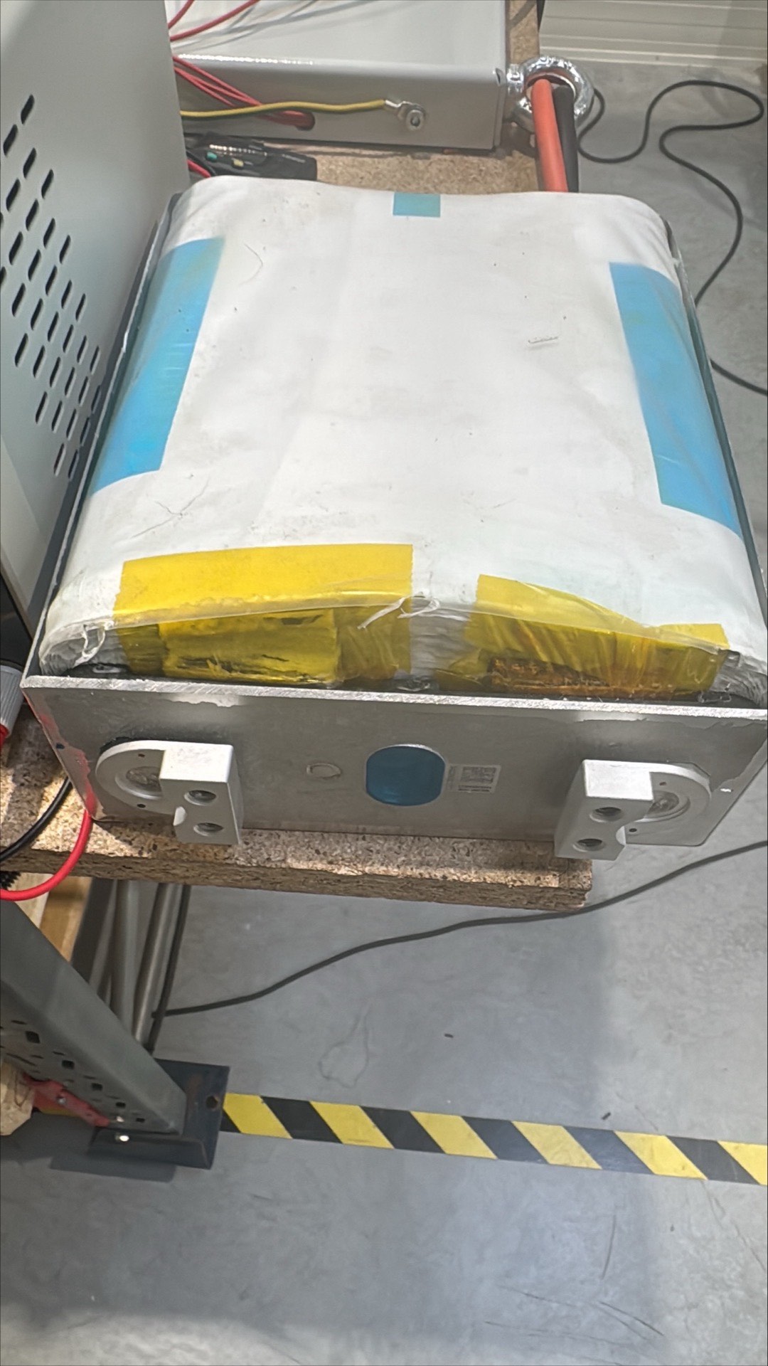
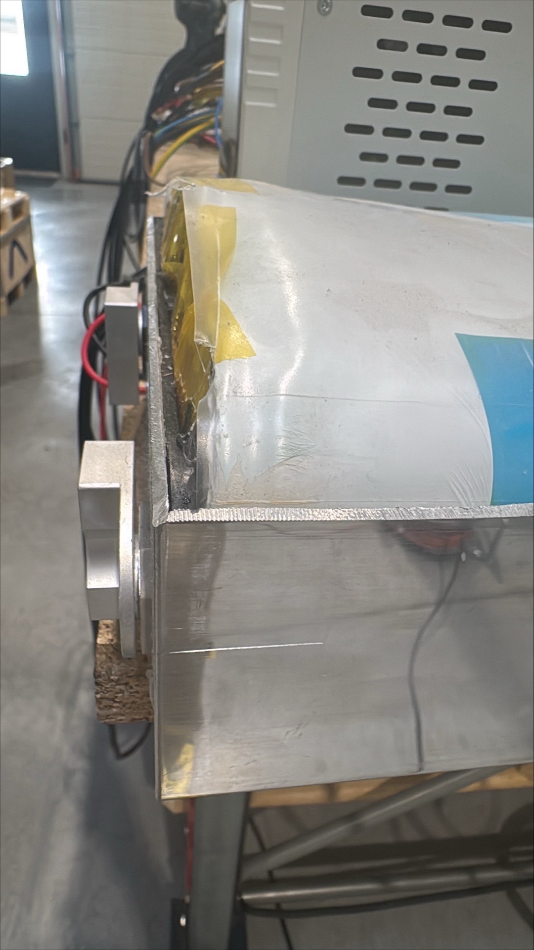
A prismatic cell arrives as a sealed aluminium can. Inside, the active electrode stack fills the broad body of the cell while the terminal plate sits above it. These are cells from the Bessify build, opened during development.
314 amp-hours, and the whole of it is one wound stack in an aluminium can.The terminal plate is a separate piece. The gap between it and the top of the stack is why a reading taken at the terminal is not a reading of the cell.
Heat reaches the terminal through the tabs, the void above the stack and the can walls. A terminal reading is therefore not the same as a direct reading beside the active material. Bessify measures the cell case along the large face and treats busbar temperature as a separate signal.
Continuous monitoring
Measure the conditions around the cells
Electrical
400 row-voltage measurements and precision system-current measurement.
Thermal
Direct cell-case temperatures, airflow and busbar temperatures build a spatial view of operating conditions.
Mechanical and gas
Continuous compression and displacement monitoring, alongside measurement of the nitrogen/oxygen mix.
Critical protective limits act through local protection paths. Fundamental protection does not depend on higher-level analytics.
Physical separation and containment
Limit the consequences of an event
Defined boundaries
Energy, Power and Thermal are physically separated to limit the routes by which an event can spread.
Pressure management
Pressure management forms part of the protective architecture of the compartment.
Retained firewater
Water is retained for monitored cooldown and controlled removal.
Testing and certification
Testing will measure the performance of the protection functions. Independent certification will assess conformity with the applicable standards.