Stored energy
Energy
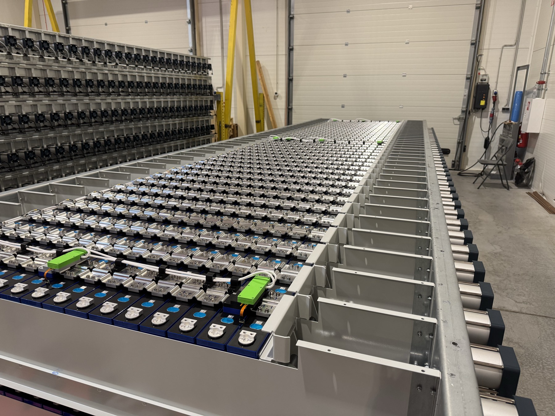
The battery cells and inter-cell heat exchangers, arranged to support thermal management and emergency intervention.
Manufactured in Estonia. Engineered and controlled by Bessify.
Bessify is a European battery energy storage system manufacturer that designs and owns every part of its system, from cell arrangement to inverter firmware. We have designed a complete 6 MWh system, with our own power conversion, battery management, control hardware and firmware. Where available components could not meet our technical or cost requirements, we designed and manufactured our own. That ownership keeps responsibility for system behaviour, firmware changes and ongoing engineering with Bessify in Europe.
The system we will manufacture is the second one we have built.
Our first 1.2 MWh system was built and tested in Estonia in 2024–25. The full-scale 6 MWh system is in production. We are documenting its assembly and checks to establish the process for repeatable manufacture.
A complete grid-scale battery energy storage system: designed to deliver 6 MWh of usable alternating-current energy at beginning of life, configurable with four, two or one 750 kVA inverters for two, four or eight hours respectively. The power configuration is chosen to suit the project’s operating requirements. Every configuration retains the same capacity. Performance remains subject to validation.
The Energy System separates energy storage, power conversion and thermal management into three physically separated compartments, each engineered around its own safety and performance requirements. The separation is designed to limit how a fault in one can affect the others.
Stored energy
The battery cells and inter-cell heat exchangers, arranged to support thermal management and emergency intervention.
Conversion and control
Power conversion, battery management electronics and control hardware in a separate compartment.
Conditioning and gas
Gas-based thermal management, circulation and Gas Management functions in a dedicated compartment.
Thermal-runaway safety determined the architecture.
The European Commission’s Joint Research Centre describes thermal runaway as “the most dangerous safety event of Li-ion batteries.”
We designed around that event: which cells to use, how heat moves through the system, what we need to measure, how the cells are arranged and how we can intervene if one fails. Those questions shaped the physical system.
Managing the cells in normal operation and retaining the means to intervene when one fails are part of the same design.
We chose gas-based thermal management and developed three separate compartments around it: Energy, Power and Thermal. Thermal mapping informed how we arranged and cooled the cells. We built higher to accommodate the architecture within the required footprint.
Understanding operating conditions and informing protection depend on three measurements: cell temperature, row displacement and current. That is why we developed our own sensing where the design required it and invested in precision current measurement. Fundamental shutdown acts through hardware, independently of higher-level analytics.
Cell selection and traceability are a core part of our safety architecture. Each cell arrives with factory measurements, which we follow with our own checks before installation. Its record then follows it to its position in the system. In operation, the design maintains cell compression and measures row displacement.
The cell arrangement is designed to provide paths for cooling and emergency water intervention. TRPPS 1 uses the Thermal System in Gas Management operation with inter-cell heat-exchanger (HX) cooling to limit propagation. TRPPS 2 provides independently triggered water deluge and progressive flooding when its configured release condition is reached.
Together, these decisions form our multi-layered propagation-prevention architecture. Protection performance remains subject to physical testing and validation. System certification is not yet complete.